Showing posts with label LL3DLGLD. Show all posts

Thursday, February 16, 2012

Time to learn and teach again

I am on a mini break right now. I'm testing and optimizing the engine to get it ready for heavy duty lifting so I'm not adding explicit new features for about a week. I optimized it down to 14 / 2.4 ms (two key values in milliseconds, the lower the better). Found an experimental way to make non-animated trees have zero impact on scrolling speed.

I also continued my experiments with making the engine do stuff it was no designed for. I'll talk about that soon. I am also preparing to bring back scheduling. Once the main scheduler is back, all tasks should be re-enabled one by one in a fairly fast succession. The target is to get the game at comparable levels to its 2D version by (the end of) March.

I am preparing to bring back the LL3DLGLD series, this time with the subject of shaders and more didactic than ever!

I also did some research in getting the game to look more modern. Increasing the poly count is out of the question, so I though I should investigate some effects. Here is bump mapping:


The bump map was produced by grayscaling the texture and converting it to a normal map without the actual geometry of the object involved, so it is far from ideal, but the result is not that bad. Here is parallax mapping:


I like bump mapping result better, especially since parallax mapping is darker, but it gives good results on closeup view:


The only problem is that using these effects makes everything look dark. I was showing you the light side of the object, but here is the dark side:


Unacceptable for an outside scene. After a lot of investigation I found the cause for this: Irrlicht is limited to two lights when using these effects. And I can't figure out a way to create and outside scene lighting only with two lights. 

Before I continue, let me show you another bump mapping sample, this time with a normal map created based on geometry:


Not perfect, the little circular bumps on top being particularly bad. Anyway, I only spent 5 minutes creating this map and it works as a proof of concept.

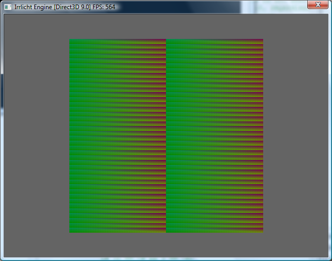
I also discovered this effect:


This effect accentuates the actual polygon structure of the object, but unlike flat shading, the margins of polygons are rounded and the shading is made to be uniform on each individual face. Not very useful, but cute!

So what can we do about the two lights limitation? I think the only solution is to take some third party shaders and use them. I found some but they don't seem to work for me. Probably because I don't know a thing about shaders.

I probably won't be able to maximize the potential of the engine without using shaders eventually, so I guess the path of least resistance is to learn and master shaders.

So if you are interested in learning shaders, keep an eye out for the continuation of the series!

Friday, October 7, 2011

LL3DLGLD – 11 – I see you, jakesillyminer

Let’s add the final piece to the puzzle: the dwarf first person camera. Irrlicht has already a built in first person camera, but I looked over the code and it would be hard to make it behave the way I want to. So we are going to write one. Actually, we are not going to write a specialized camera class like Irrlicht has for different roles; we are just going to create a normal camera and make it behave like a first person one only by handling keyboard and mouse movement. There are a few popular first person models and behaviors in games out there. I’ll pick one that I like the most. For starters, mouse look will be what I call normal: moving the mouse up (away from you) will raise your head and moving the mouse down (closer to you) will lower your head. Some people out there suffer from a very strange condition and consider this model to be “inverted”: they want to look down when you move your mouse up. This behavior is even more confusing when you play something with a game pad. What up for a mouse means can be debated if you are silly. But you can’t debate that for a thumbstick. In the future I might add the option for inverted controls to cater for all audiences. For 4.99$. 

Another convention that I will be adopting: directional keys or WASD are for forward, backwards and strafing. No turning. You turn with the mouse. 

Before I continue, let me explain again how the world is set up in 3D space. This passage will be doubly important to people who would like to send me some meshes. Let’s consider that you are standing somewhere in the middle of a perfectly horizontal surface. Your head points to the north. You raise your arms sideways, with your left arm pointing exactly to the west and your right to the east. Like a lot of humans before you, you consider yourself the center of the universe: the origin point (0, 0, 0) is exactly under your feet. The X axis goes along the line created by your arms, with left/west being negative and right/east being positive. To the north, the direction you are looking at in front of you we get the positive Y coordinates, and behind you we have the negative ones. The Z coordinate decreases as things get farther away from the level of the floor. You are very tall and have a height of exactly 2 meters, so the top of your head has a Z coordinate of -2 meters. If you were to go fishing, a 100 meters deep lake would have its bottom at 100 meters on the Z axis and you would look form -2 to 100 over a distance of 102. I hope I did not confuse you even more. 

On the other hand, 3D modelers should be fairly familiar with this model as long as they mind the Z axis. 

So the first step is to set camera coordinates. We determine the Z coordinate based on elevation and set the rest to zero for the camera position. We do the same for the target, but this time we increase the Y coordinate with some number. I put 100 and need to test if this has any effect based on FOV (field of view). Setting these coordinates should place the camera on the floor so you probably won’t even see it. We decrease both Z coordinates with the height of a dwarf and this should fix it. If it does not work we check the camera up vector, which should be (0, 0, -1). 

For the first phase of movement, we add or subtract the same constant form either the X or Y axis for both camera position and target. For forward we add to Y and for backwards we subtract. And we modify X for strafing. And that it. Now we have a four direction smooth strafe. 

Next we add camera look with mouse. To achieve this I’ll keep the same camera model and rely on camera rotation. Irrlicht can adjust your camera target based on camera position and camera rotation. To achieve rotation we rotate on the X and Z axis. By setting the starting X rotation to -90 degrees and the Y rotation to 0 we get the same north facing viewpoint. 

Then we set the mouse cursor to center of the screen and keep this center in a variable. We create another variable for the mouse position that we update every time we get a mouse move event. We use relative position with floating point numbers. Every time the current position is different from the center, we calculate the X and Y difference, update rotations and set the current to center. Getting the X and Y is as simple as: 

float y = (0.5f - cursorPos.Y) * 100
float x = (0.5f - cursorPos.X) * 100 

And that’s it again! Mouse movement triggers head rotation. For the final step we must make forward/backwards movement take into account these angles. I tried a lot of complicated matrix and vector math, but in the end I solved this by the simplest formula ever. Forward: 

  • AdjustCamera(-sin(rotz * M_PI / 180), cos(rotz * M_PI / 180), 0); 

Backwards: 

  • AdjustCamera(sin(rotz * M_PI / 180), -cos(rotz * M_PI / 180), 0); 

Let’s see all of this put together in video form: 


Things are not perfect yet: 
  • Proportions are a little of. Dwarves are too small. Trees are too big. Walls are about right. 
  • I’m not sure about the FOV. Need to experiment with a lot of different values. 
  • Pressing two movement keys at the same time composes the effect and you move faster. Need to adjust for this. 
  • Need to adjust for framerate. With FRAPS reducing my framerate to around 30 I ended up walking slower than usual. You should have the same movement speed with all framerates. 

But still a nice result. Did you notice the dwarf? It comes with Irrlicht and I have no idea why the default animation is tee bagging. I swear I did not do this on purpose! Or did I? :P 


And I can’t shake the feeling that at least one of the coordinates in my space model is inverted! GAAHHHHH!!!! 

Friday, September 30, 2011

LL3DLGLD – 10 – Slice 'Em Up!

I was pretty much decided not to post today. I had enough posts for this month, well over quota and I'll be out of  town for the weekend. But I ended up recording a few videos, so I might as well get it out of my system

I implemented vertical level slicing. You couldn't really play if the world wouldn't be represented as if sliced at your current level, not even with 3D. To make things more manageable, the map cursor is bound to you current level. I really need to implement some visual aid that will guide you on how high up your cursor is when moving it in the air and not on a solid surface. Also, replacing the cursor with something else that is not a white box could help a lot I think.

Normally I would go into detail, giving some instructions on how to do slicing, but this topic is self explanatory, especially since I do not slice in the middle of a level. Even if I would, slicing is very simple since I am using a horizontal plane intersection as the slicing point.

Current level slicing is a fairly common feature found in a number of games. I also implemented a second slicing layer bellow the current level, which is always a fixed amount below the current one. This fixed amount can be changed with Page Up/Page Down, even though these keys would be better suited for level select. This second slice level is not that common and it has two uses: sometimes it can help with keeping you focused on a portion of the map, but the real reason is performance. If you don't have enough juice in your machine, decrease the distance between the planes.

I also smoothed out camera movement and except for an awkward disorientation after changing from top down/isometric to full 3D fly camera, I am fairly happy with it. Tree LOD needs to be adjusted a little.

I added a few statistics on the screen, as FPS, total number of triangles the scene is composed of and the number of triangles that actually get sent to the GPU. As said, currently the engine is not smart enough to cull the triangles that are behind the camera, so all the triangles of the scene are processed. Some are still culled automatically, but once I can exclude these triangles from the entire rendering process I expect a noticeable FPS increase. But FPS is good. FRAPS reduced it to 60 and then 30 in the video, but without it I can't really complain. When I get my hands on a weaker computer I can give you more info.

I also greatly improved stability. The 3D engine used to crash a lot. Now I had hours without a single crash. It used to crash due to something happening in the Irrlicht code and I think it is related to the reference counting memory manager from Irrlicht. Out of all the memory management schemes reference counting is probably the most stupid, and Irrlicht version is particularly poorly designed in my honest opinion as a professional. Reference counting at its best frees you of the burden of manual memory management. But with the scheme from Irrlicht, you exchange manual memory management for manual reference count babysitting. I want to keep this blog family friendly, but I am so close to showing Irrlicht a more interesting vocabulary choice in written form.

With these new changes, the engine is ready to tackle all shape related issues. The stuff I do with the shape (what stone is inside) is not fully implemented yet, but the engine can now handle any world of any shape and the code is ready for the next step: becoming a client of DHCore. DHCore is my semi general use game library specialized in this genre of games (which I want to make available in some form or another someday when I have the time; now I need to catch up on my schedule because of the unplanned 3D conversion). The 3D engine does not use DHCore yet, but DwarvesH (the game) and its editor use it. So once the 3D engine becomes a client of DHCore, all the functionality from DwarvesH should work out of the box with the new 3D engine. Theoretically. I have a feeling that it is going to need an intense QA period. Oh, and I need some 3D models.

Here is a video with the slicing mechanism in action. This will be the last video/content that does not use DHCore:

Thursday, September 29, 2011

LL3DLGLD – 9 – Spycam

Finally! I have a functional camera system. I am not going to talk about the implementation because I would rather forget about it, so I am going to talk about each camera mode.


Top down camera
This camera mode is very similar to the top down 2D mode that was available in the 2D engine. That classical 2D mode will definitely be removed since the 3D one is a lot more powerful. In this mode the user controls the mouse cursor by moving the mouse, directional keys scroll the map and we have smooth zoom. I need to add a camera tilt option, so you can view the scene from a top down but angled view point.

The question is what to show with this mode. I decided that I will center the camera on the currently selected level and keep a constant distance every time you switch the level. Without this, the user would almost always follow a level change operation with a zoom operation, because the perspective causes different levels to have different sizes. So levels above you current level won’t be rendered by default. Rendering levels below the current level has some merit to it, especially if the current level has holes in it, so I’ll render a few levels bellow, but probably not all the way down to level zero.

There is one issue with the entire engine: my LOD algorithms work extremely well with first person cameras that are positioned at the eye level for dwarves. It does not work that well with other camera. If I write a special LOD algorithm that takes advantage of the special square shape of the map in this mode, I could obtain a framerate that is higher than in any other mode.


Angled camera
This mode is very similar to the 2D isometric engine, with the difference that this time we have perspective.

Zooming now works fast and without using tons of memory like it did with my failed attempt at providing this feature with a software based approach.

I’ll keep the camera focused don the current level, like I’ll do with the top down mode.

Here, my current LOD works against the specifics of this view mode. A more specialized LOD would increase performance and keep objects on the side of the screen from switching over to low LOD, but writing this specialized method will be harder than in the top down mode.


Fly camera
This third mode is the one I have been using in my previous videos demoing the 3D progress. You start from up in the sky looking down and you move like you do in first person shooter, but flying without gravity. This is an exploration mode and right now I have no plans for allowing you to interact with the world.


First person camera
And this is the final mode that will allow you to jump in the body of one of your dwarves and look around with his or her eyes. Time will stop and you won’t be able to interact with the world, but to make it more fun I’ll allow you to walk. This mode is not implemented yet and will be very similar to the Minecraft experience, except for not building anything because it is an exploration mode.

Here is a video demoing these camera modes:

Monday, September 26, 2011

LL3DLGLD – 8 – Become a real engine

OK, I am done playing around! I think I have gathered enough knowledge and working snippets of code to put them all together. Here is what we get:


Time to take these random pieces of code that I have been tinkering on for a week and that can be considered a solid starting of point and create a real engine.

The first step is to optimize the creation of vertices based on the logical strips. The new system is less flexible, but faster and a lot easier to use.

The second step is to greatly optimize the actual strip creation. The new method is roughly as fast as the previous one, but a lot shorter. How short is it? Well, it is SHOOOOOOOOOOOOOOOOOOOOOOOOOOOOOOOOOOOOOORT! Combining these two methods the engine has lost 300 lines of code and now the terrain supports elevation. Elevation still uses a random and quite poor terrain generator, but next time I’ll plug in the real terrain generator from the 2D engine to get some better results.

I also added the ability to switch on and off the use of low LOD grass and trees. Needless to say, each time you turn off one of these optimizations framerate drops. Grass with or without LOD looks almost the same and I’ll leave it off for strategic and first person camera because you will barely be able to tell the difference, especially with elevation. Trees on the other hand have a larger visual impact. For trees the lowest LOD is just to skip them and here it becomes very clear that not having billboards yet greatly reduces visual quality. I also restructured the engine, using good class structure and design.

Here is video with the engine in its current state (while tomorrow I’ll add the smart terrain generator from classical DwarvesH to see how it works):


Let’s talk a little about this engine. The first thing to notice is that it is ugly. And I am not talking about the placeholder cube trees. Generally speaking. And I also have a contrast problem like I did in the 2D one. Even after I add lighting and shadows, I’m afraid I’ll need the help of a professional artist to make it less ugly.

The current level of optimizations is not enough. It works fine right now, but I expect it to work less good when the real terrain is introduced. The general strip conversion is not perfect yet. Top surface conversion is good enough but sides are horribly unoptimized. And since normally you’ll have a floor on top of a wall in natural environments at every elevation change, I am actually using double the needed polygons in these cases. I removed bottoms for now.

And I couldn’t care less! Normally, I would take a couple of weeks and optimize the hell out of it. But it runs just fine for now. I spent a lot of time creating the perfect 2D engine only to discard it once I reached the limits of 2D. Instead of actively optimizing stuff until it is near perfect, I’ll do it passively. Whenever I have nothing else to do and am in a mood to optimize stuff, I’ll do a short optimization session. Over the time, the gains will add up. So performance is not going to be great in two weeks, but it will be in four months (random example periods). If I maintain the old workflow, I’ll finish the game in 10 years. I would like to get something out a little bit sooner.

Bug fixing I’ll still do in the old rhythm. And there is no use to optimize stuff right now since I have a huge glaring flaw in my LOD algorithms: I am using a distance based approach, not a frustum based approach. You are in the middle of multiple spheres and LOD is computed based on the radius of the spheres and object intersecting them. So that’s right: unless you are high up and looking straight down, you are rendering roughly twice as much as you should: the sections in front of you and the sections behind you. Once I figure out a frustum based optimization that can hide sections that are not on screen, I expect my framerate to almost double.

Sunday, September 25, 2011

LL3DLGLD – 7 – Grass LOD

I am very close to getting the floors to that point where I can easily integrate the new engine with DwarvesH and the entire floor system with all the possible actions and events will work. And since walls can be considered higher floors, adding full wall support should be a technicality.

What I need is to take the floor layer, and make it support different materials in different cells. This covers grass levels, stones and sand. Up to this moment everything was implemented without cheating, but to achieve this we’ll have to dig deep in the trick basket and there is a chance that we’ll have to change the floor model to handle the requirements and limitations of 3D.

We’ll try and create a texture that is made up out of multiple small textures: 


This is similar to mipmapping, and thus this approach will result in visual artifacts at sub-texture borders, but compensating for this is a subject for a different post. I tried to add numbers in each cell in that texture, but I grew bored of it by the time I reached number two, so I added squiggly lines so I can distinguish the cells when applied to a floor mesh:


The big texture has 8x8 tiles, 64, applied to a surface of 30x30, 900, in order. So on the third row, the first 4 tiles are the last tiles from the texture. Now we use the same texture I used in the 2D isometric engine for grass levels:


Grass levels grow in intensity from zero to 100% in wrapping strips and then start from zero again. This pattern is not a natural one, so let’s randomize it:


This is more like it! The same system I had in the 2D engine, but with the added benefits of camera rotation:


And this is where we encounter our first real obstacle: right now I am only aware of a method for creating these cells by increasing polygon count. When we go with a full map, the large number of polygons reduces the performance a lot:


Not only do we have a low FPS, but camera movevement is now severely lagging. Before I address the FPS issue, it is time to optimize everything! We start with the LOD calculation, making it only rebuild sections if really needed. We also assign a new color coded LOD system:


Normal shading is for full detail, red is level one, green is level two, blue is level three, orange is level 4 and muted/grey is the final level, the lowest quality. Here are two shots where we see the system in action from a pseudo-top town slightly tilted view point which could be one of the default camera angles:


We have the center full detail sections, but as we get farther away from the camera the sections switch fast to low detail. With this LOD calculation and optimization method, camera movement is as smooth as could be. The FPS did not change, because we are not doing anything with the LOD info right now. Time to change that! Let’s try something simple first: we’ll assign full grass texture to the lowest LOD level, ignoring the actual grass levels:


Nice!!! If we try extending this to two more low levels, FPS no longer takes a huge leap, but it is still something you can notice.

The system works wonderfully in both the FPS mode, when you are very close to the action, and in the top down tilted mode. And I guess this is as much as you can ask. Once you start removing the restrictions on the camera, we get a small problem that had a life as long as 3D graphics: pop in! I think it is best to illustrate this with a video:

Saturday, September 24, 2011

LL3DLGLD – 6 – So close

The first stage of my investigation and research is slowly coming to an end. There is one more thing to do before starting stage two: optimizing the hell out of double strips. My performance is not as good as it should be. I have a floor layer that has a top surface, a bottom surface and side surfaces when needed. Sides are optimized (only added where needed), but only one by one, not as a strips. Then I have a wall layer with the same structure. The problem is that if in the same cell we have both a floor and a wall block, the top side of the floor and the bottom side of wall are identical and neither should be created. The bottom side of the wall is invisible normally because it is facing away the camera, but to better illustrate my point, I’ll make it face the camera and remove the side surfaces so you can see what is going on inside:


The extra redundant layer is clearly visible. First, we optimize away this layer. My maps are random, so I can’t give the exact same shot twice, but this one is close enough:


If everything behaves as expected, I have practically reduced to half the number of polygons the wall layers uses (only top + bottom) if the entire floor is intact. But there is still a problem. I may be no longer rendering extra wall bottoms, but I am still rendering extra floor tops. Let’s fix this:


And now, for the final shot, with all sides rendered as needed:


Performance has definitely improved, but there are two downsides. First, I am doing a lot more CPU work while determining what part of the mesh to create. So my map scroll/camera rotate operations are not as smooth as they used to be. This can be improved a lot by creating better algorithms. The second problem is that the visual artifacts have become more apparent and some new ones have appeared. I though it was the same problem that is causing the artifacts mentioned in the previous post (and it may be so), but upon further investigation it seems that an extra strip is added sometimes on top of an existing one. I tried to fix it, but kind of ruined it, so I reverted. Anyway, these problems are not that severe. Quite normal actually for something hacked together in a few days while still learning.

I can’t just stop on this note, so I’ll leave you with an early preview of things to come:


And finally, a close-up:


Performance has degraded considerably, but the trees are really poorly optimized. But the new experimental engine can render pretty much as much as it could the first time I presented a 3D engine, but only render. Last time you could interact with the world normally. I am working just on rendering right now. But the big difference is the performance: while the performance is pretty bad, it is at least a hundred times better than last time. Last time it was so bad, I had to abandon the 3D engine because it was unplayable. A GeForce 8800 GT was struggling to keep a double digit framerate.

So the new engine looks promising!


Friday, September 23, 2011

LL3DLGLD – 5 – (p)LOD

We need to add some final touches for this very early single level map geometry renderer: the wall layer must get as smart as the floor layer. This process involves basically doing what I did for floors again, but this time for walls. It is something that is some work, but not much new can be said about it.

So we’ll take a little detour and talk about LOD. Level of detail is a very important concept. It allows you to render the same entity with varying levels of detail so that you can use high detail when something is close and low detail when something is far. The high detail would not be visible on far objects and it just wastes processing time.

I have no idea what the standard way of doing LOD is and if there is some built in support in the GPU or one must do it all manually within the engine. One thing I do know: I can’t do LOD checks for every single entity (tree, plant, animal, dwarf, …) in the game world. Processing all these entities (which I have tens of thousands, if not hundreds of thousands on the same map) takes enough CPU time with all the things the game does even without trying to render them. Adding a new LOD check for each entity would be impossible unless using high end computers.

So I’ll do a LOD check for each section of the map. Maybe there is a standard way to assign a LOD factor to such a section. Something tried and true. I don’t know. So I’ll be using my own slightly heuristic methods. Method number one could be to measure the distance from the camera to the center of the section. Method number two could be to use the minimum distance from the camera to the four corners of the section. I will be using method number two. So here is only one section, very close to the camera:


As we move away, it becomes darker and darker:


In the final shot, it is almost black. Now if we render then entire 300x300 map, we get these results:


It will take some trial and error to determine how “dark” a section at a given distance should be. First, I must do something with this LOD information. Right now I am only computing it, but the possibilities are endless. Let’s take trees for example. At the highest LOD/closest section, the entire section could be rendered with full high polygon models for the trees. Sections that are a little more distant could be rendered with low poly trees. Even more distant section could be rendered only with two 3D stretched cubes, one for the trunk and one for the canopy, with very low resolution textures. Going even further: billboards. And the most distant sections won’t render trees at all. This is only an example. I don’t know yet how many levels of LOD I’ll be using and how much is overkill.

And now back to business! We take this very simple wall pattern:


Update the algorithm to handle holes like we did for the floors:


And use a better, but still placeholder cliff side border algorithm:


Here are a few extra shots:

LL3DLGLD – 4 – Poke

The saga continues! This time we’ll enhance the existing system in order to bring the engine closer to being able to render a floor layer. For starters, we’ll consider a single object and poke some holes in it:


The holes behave correctly, as we can see by investigating both sides:


This is the perfect opportunity to enable strip color coding and see how we created these holes:


So we have one object consisting out of a set of stripes that fill the surface between holes. The number of vertexes has increased to 1392. And we have 696 triangles. I’ll leave as homework the determination of the relationship between the number of triangles and the number of vertices. Now we can experiment with random patterns:


I’ll enable wireframe mode so you can see the triangles in action:


The most intensive object can be created by alternating between full and empty cells. It is sufficient to only do it on the horizontal axis since strips are only created horizontally. Using this method, we determine that the maximum number of vertices is 3600 for the 30 cell section:


Using this pattern and keeping the number of objects constant, we can see the worst case scenario FPS:


Te number of vertices has grown so much that we only get 60 FPS. This scenario is almost impossible in practice. Sure, a player might try and poke holes in a pattern specially created to reduce framerate, but during normal play you won’t encounter this scenario. And if you do try it, your reward will be reduced framerate.

For the final touches, we add a small rectangle on the south side:


And we continue to add the rest of the sides. I messed up a few texture coordinates or what not and some textured are flipped around, but I won’t worry about that:


Here is the end result, with all borders filled:


Using the worst case scenario, the polygon count is now up to 7320. The generation of sides is not optimized yet and probably it can be reduced. The worst case scenario is also down to 33 FPS. So I optimized it a little and now it is between 7200 and 7260. Random hole maps have worst case 43 FPS and up to 100 (with around 5000 vertices).  And maps without holes have around worst case 400 FPS.

Tuesday, September 20, 2011

LL3DLGLD – 2 – Strip

When we parted ways last time, we came to the conclusion that we cannot build our world from small objects, like LEGO blocks, and we need to be more clever. Instead of using cubes, we will be using horizontal strips with a maximum width. Then later we can further optimize it by leaving out invisible strips, but in the beginning we’ll just be happy to have the strips working.

Since we can’t use Irrlicht primitives for this, we’ll fall back to vertex lists. Oh, what joy! To keep things simple, I will only concentrate right now on strips that are on the “top”. The top of a cube is a small rectangular plane section, and putting such sections in sequence will create strips.

We first want to create such a plane section, a rectangle. Using vertexes and triangle strips, we’ll need two polygons and four vertexes. Let’s create the first triangle: we create a vertex at coordinates (-5,5,0), the second at (5,5,0) and the third at (5,-5,0). This way, if we consider our triangle an object, it would be “centered” on the origin. But 3 vertices does not a triangle make. We need to give the order these vertices will be used to create the polygon: 0, 1 and 2, nice and straight forward. Here is the triangle with texture, but color coded (green is the first vertex, red/purple the second and yellow/orange the third):


To create the second triangle, we need one additional vertex with the coordinates (-5,-5,0) and since we already have 3 vertices whose coordinates are appropriate for the creation of the new triangle, we’ll reuse it, creating a triangle out of the vertices with indexes 2,3 and 0:


Then we parameterize a little our creation, and now we can create such “strips” as normal objects. Let us create 11 such objects, aligned on the Y axis:


So if these strips are normal objects, then won’t these objects suffer the same limitation as normal objects in regards to total number count? Yes, they will, but since we parameterized strips, we can create them with any width. Here we have the same number of objects, but with strip widths going from 1 to 11:


The only problem is that the texture now gets stretched. We can fix this:


Pretty good, considering I have absolutely no idea what I’m doing and had very little knowledge on this subject before researching to write this post. Let’s see these stripes again, but without color coding:


I’ll reactivate the color coding and keep it on for the immediate future because this way I can easily tell visually where a strip starts and another ends. Using these strips, we can create a larger rectangular area:


And use multiple such "boxes" to create larger areas, like this one that is equivalent to 40x40 cells:


And for the final test, we go with the 300x300 map:


A good start: almost 30 FPS and smooth scroll and camera movement. This is for the entire map visible, the worst case scenario. While scrolling around on smaller portions, we get between 60 and 90 FPS.

I realize that what I am doing here is child’s play. These techniques are very simple and I hope to be using some engine that does a lot of complex optimizations on its own. But in order to understand, use and even appreciate these potential optimizations, I must understand a few things on my own.

Join me next time when give a little shape to these planes!